Stepper actuators
A NEMA 17 stepper, a 9:1 gearbox and an optional AA360 absolute encoder in one sealed, printable housing. The precision and predictability of a stepper, with servo-like absolute position. Two lengths, one design.
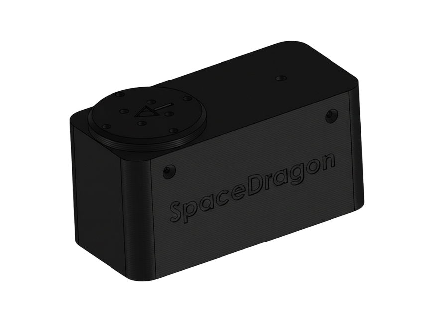
Between hobby servos and FOC actuators
Cheap hobby servos are limited in mechanics and resolution. BLDC/FOC actuators are expensive and complex to integrate. These actuators sit in between: precise positioning and predictable behaviour under load with a controller you already know.
Absolute output angle
With an AA360 encoder inside (AS5600 or MT6701 version), the output shaft reports its true angle from power-up, so no homing is needed.
Standard drivers
No electronics inside: wire it to a TMC2209, TMC2208 or any bipolar stepper driver.
Continuous rotation
No internal angle limits. Travel limits, if you need them, live in your software.
Sealed passive cooling
Internal airflow channels spread heat through the housing. No vents for dust to get in.
SA1737 or SA1755?
| SA1737 | SA1755 | |
|---|---|---|
| Holding torque (calculated) | 3.6 Nm @ 24 V, 0.5 A | 5.5 Nm @ 24 V, 1 A |
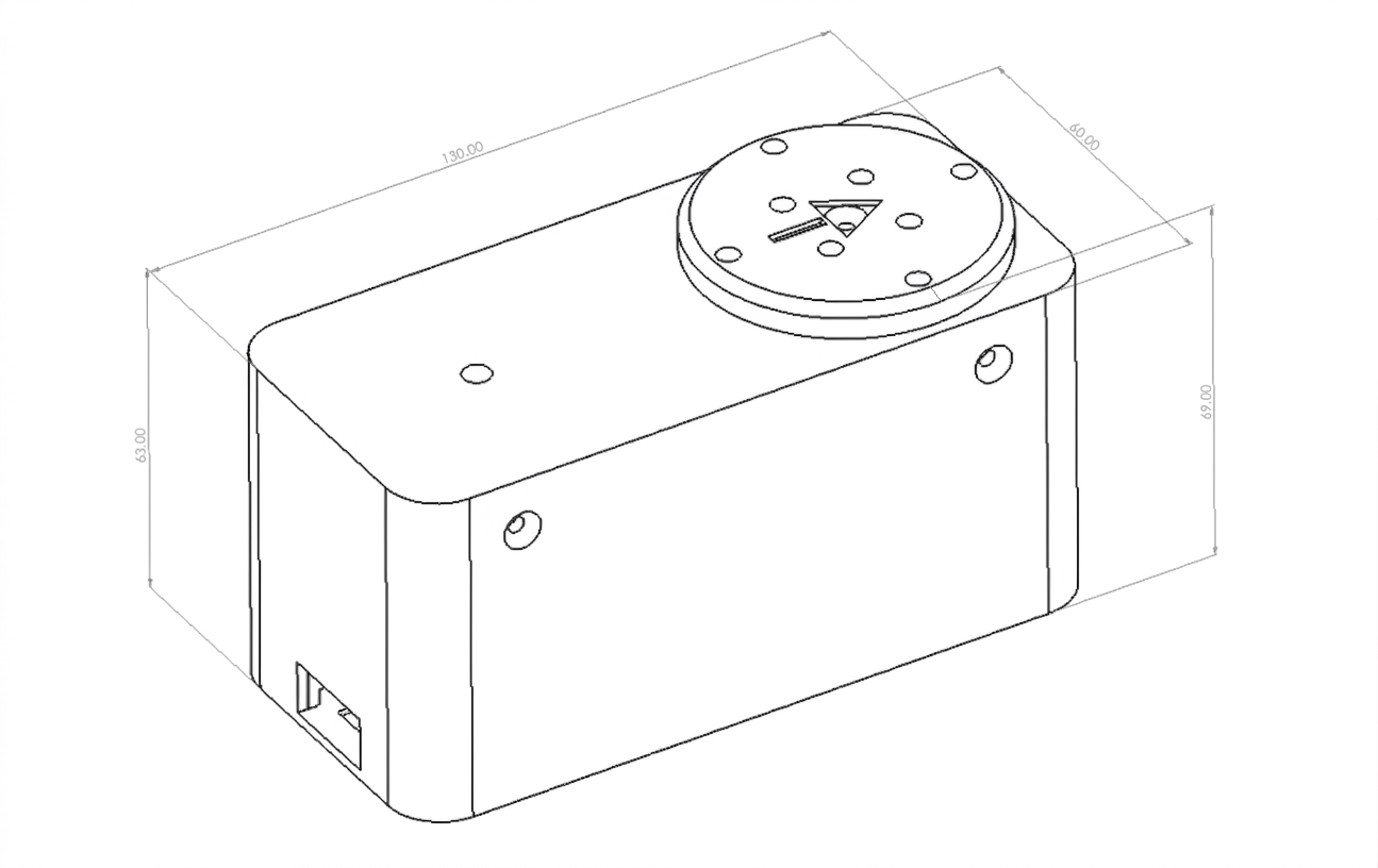
| Dimensions | 60 × 130 × 69 mm | 60 × 130 × 91 mm |
| Weight | 530 g | Not yet measured |
| Motor | NEMA 17, 1.8°, 200 steps/rev | NEMA 17, 1.8°, 200 steps/rev |
| Gear ratio | 9:1 | 9:1 |
| Backlash | < 1° | < 1° |
| Motor supply | 12–24 V | 12–24 V |
| Gear efficiency | ~90 % | ~90 % |
| Recommended housing material | PCTG-CF | PCTG-CF |
| Operating temperature | −40 to 65 °C | −40 to 65 °C |
| Max. housing temperature | 70 °C | 70 °C |
| Free files | Cults3D | Cults3D |
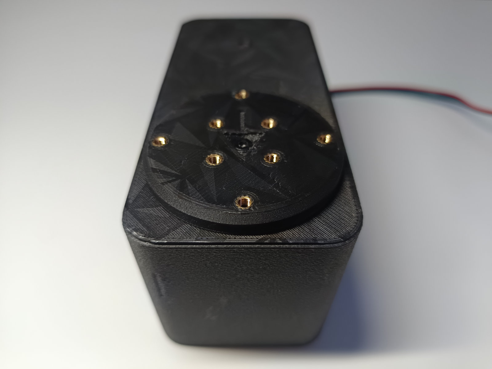
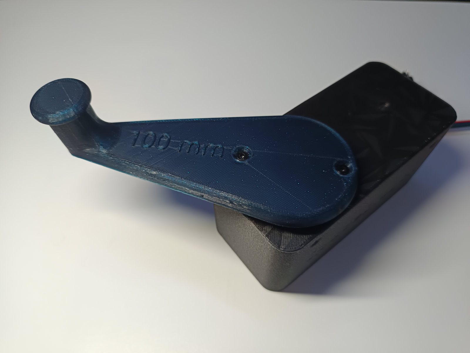
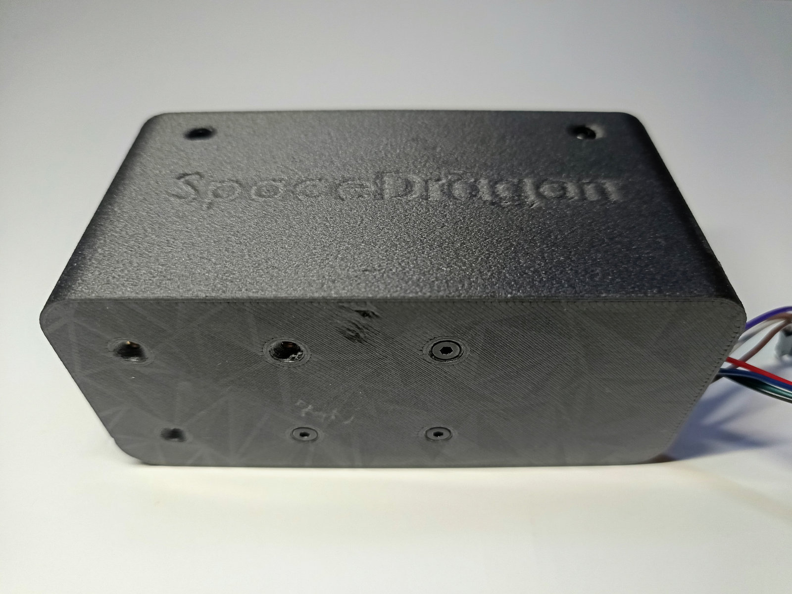
Drawings and photos
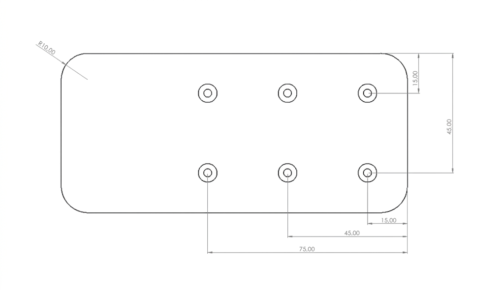
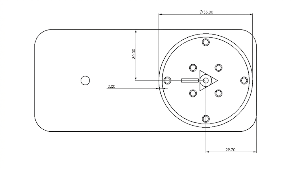
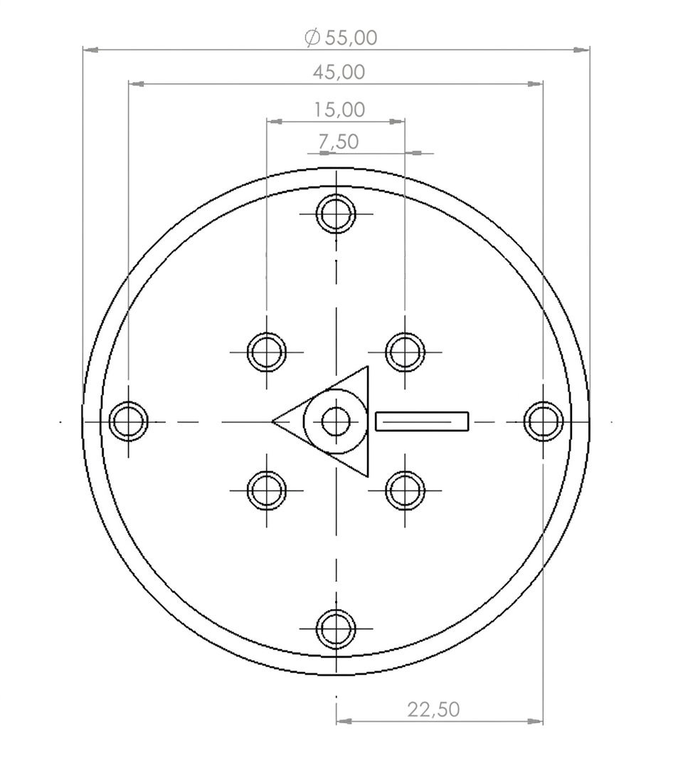
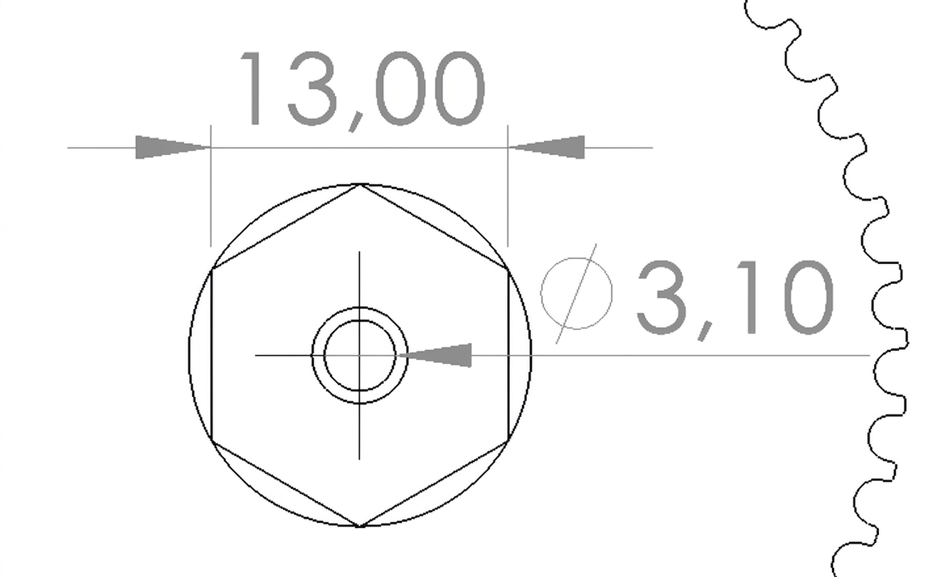
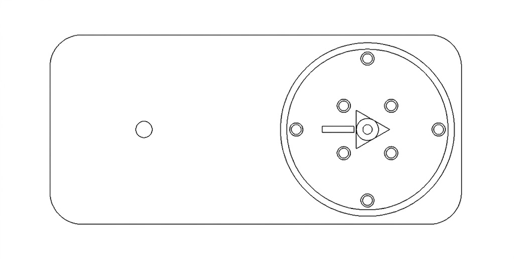
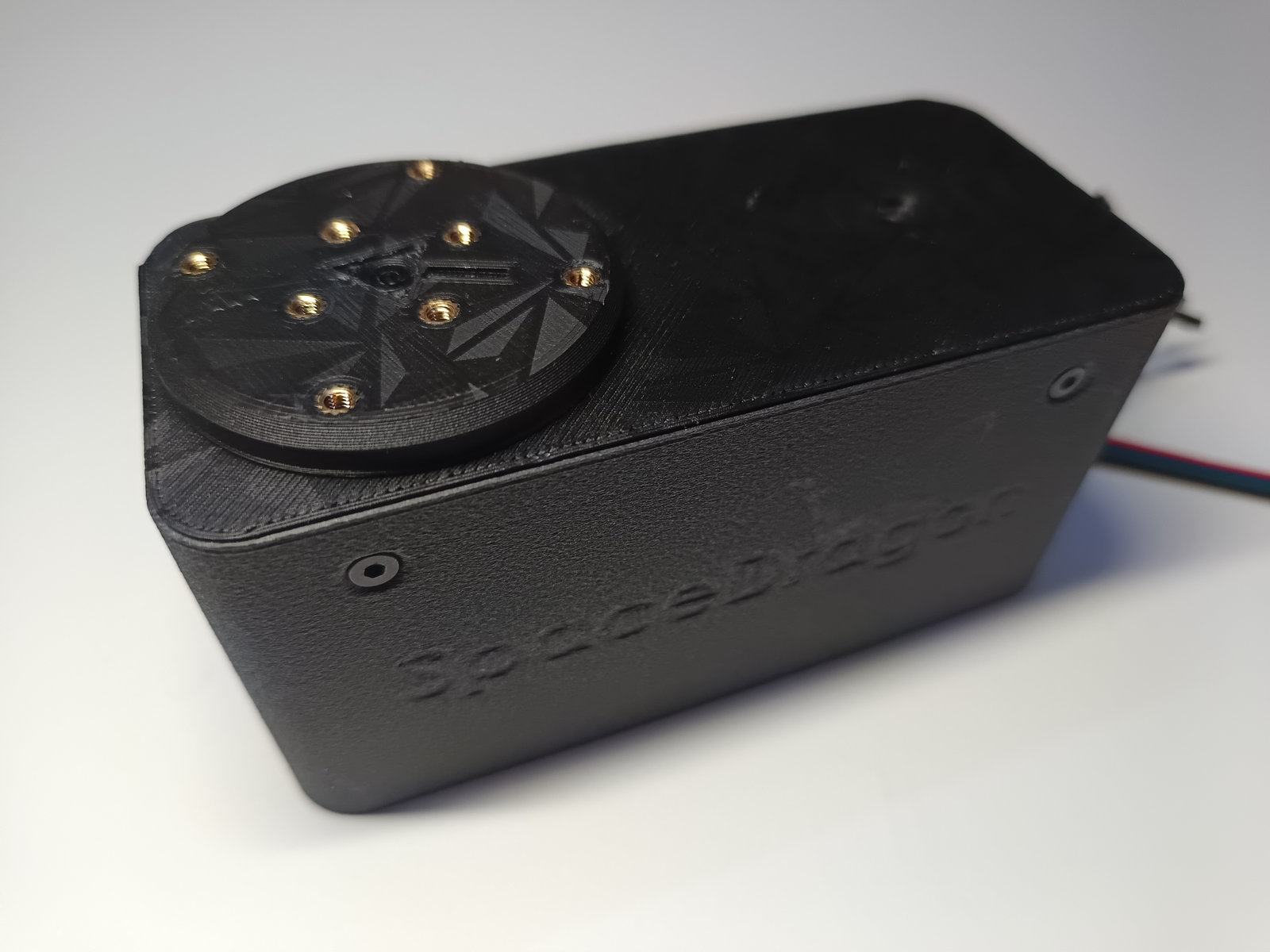
Drawings show the SA1737. The SA1755 is identical except for its 91 mm length. Click any image to enlarge.
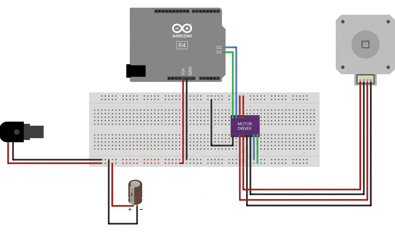
What you need to add
| Stepper driver | External bipolar driver, e.g. TMC2209 / TMC2208 |
|---|---|
| Controller | MCU, SBC or motion controller generating STEP/DIR (Arduino recommended) |
| Motor supply | 12–24 V DC, minimum 12 V 1 A |
| Bulk capacitor | ~100 µF on the motor supply |
| Encoder supply | Separate 3.3–5 V logic supply (if encoder used) |
| Motor connector | JST 6-pin |
| Encoder connector | 4-pin Dupont |
| Cooling | Recommended for continuous duty or warm enclosures |
Mounting tips
- Use a rigid mount. Flexible brackets in torque-carrying joints cost you precision.
- Don't use the output shaft as a structural support for bending loads unless your design accounts for it.
- Keep shaft, coupling and housing support aligned to avoid extra friction and side loading.
- For DIY prints use PET, PCTG, PETG, PA or PC with HDT above 60 °C. Printer tolerances can increase friction and backlash.
AA360 encoder inside
Both versions of the AA360 fit inside the actuator: the MT6701 version (14-bit, used in the datasheets) or the AS5600 version (12-bit). The zero reference points to the front of the actuator. Use open-loop stepping for simple mechanisms, or close the loop in software when the task needs persistent output-angle awareness.
| Wire | Signal | |
|---|---|---|
| Red | VCC (3.3–5 V) | |
| Black | GND | |
| Green | SDA | |
| White | SCL |
| Value | |
|---|---|
| I²C resolution | 14-bit (0.022°) |
| PWM / analog | 12-bit |
| I²C address | 0x06 (alt. 0x46) |
| Angle registers | 0x03–0x04 |
| PWM frequency | ≈994 Hz or ≈497 Hz |
| Supply current | 10 mA typ, 14 mA max |
| Value | |
|---|---|
| Resolution | 12-bit (0.088°) |
| Outputs | I²C, plus analog or PWM on the OUT pin |
| I²C address | 0x36 (fixed) |
| Angle registers | 0x0E–0x0F (ANGLE), 0x0C–0x0D (RAW ANGLE) |
| PWM frequency | 115 / 230 / 460 / 920 Hz (selectable) |
| Supply | 3.3 V or 5 V |
Power it up safely
- Verify mechanics. The actuator rotates freely and the load path doesn't bind the gearbox or shaft
- Set driver current. Start conservative before energising the motor
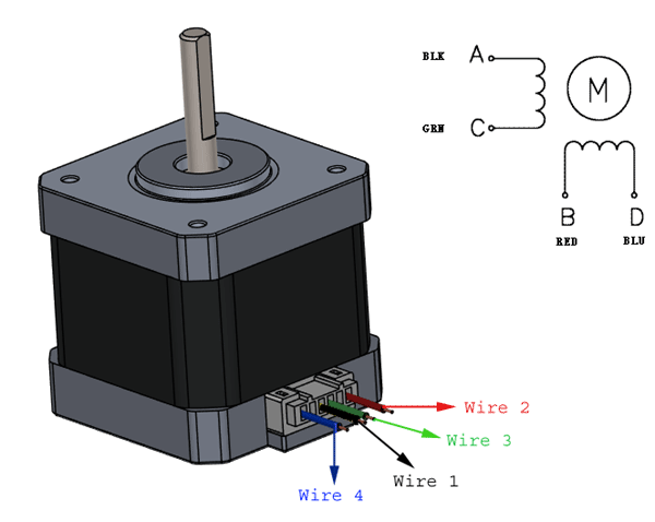
- Verify motor wiring. Confirm phase order, or test at very low speed first
- Verify encoder wiring. Check VCC, GND, SDA and SCL before applying encoder power
- Start slow. Low speed and low acceleration for the first move
- Confirm direction. Real direction matches what your software expects
- Confirm feedback. Encoder angle changes smoothly in the expected direction
- Raise limits gradually. Increase current, speed and acceleration only after checking temperature rise; keep the housing below 70 °C
Datasheets and guides
Join the SpaceDragon community
Follow development, ask questions, share your builds and help shape the next projects.